What is cantilever in architecture?
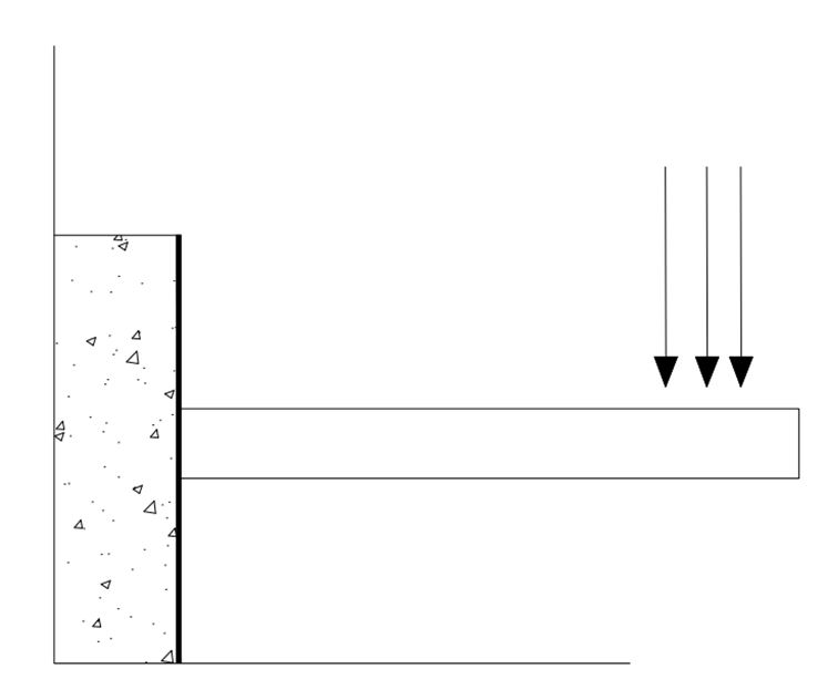
A cantilever beam is a flat, rigid structural support that is fixed or anchored at one end and, on the other end, free or projecting horizontally, transferring all vertical load to the beam and the wall. A cantilever, like other structural parts, can be shaped into a beam, plate, truss, or slab. The top half of the thickness of such a beam is subjected to tensile stress, which tends to lengthen the fibers, and the lower half to compressive stress, which tends to crush them. As a result, it is sensitive to shear stresses and will deflect in response to a force; the amount of deflection is determined by the shape of the cantilever and the material used to construct it.
Cantilevers are widely used in building construction, engineering, electronics, machines, physical science, and average houses. In construction, any beam that projects out of the wall and has free projection is considered a cantilever. Longer cantilevers in a building require more clear space. A cantilever building enables overhanging structures to be built without the need for extra support.
Design of a Cantilever Beam
A cantilever beam is a beam that is simply fixed at one end, and the other end is free of any support. This type of beam is statically determined, which means the reaction to the outside forces can be predicted by calculation and using equations of static equilibrium. [1] Under the action of a structural load, a cantilever beam is subjected to moment and shear stresses. The main objective of any design process is to transfer these stresses safely to the main support.
The bending moment of the cantilever beam varies from zero at the free end to the highest value at the fixed end support, as shown in the figure 3. below. As a result, during the design of cantilever beams, the major reinforcement is provided to the upper fiber of the concrete in order to safely hold on to the tensile stress.

Considerations while going with the span of the cantilever beam:
- The depth of the beam
- Type, magnitude, and location of the load.
- Type of material selection and quality of it
- One of the ends of the cantilever beam should be properly fixed to the wall or any other support to reduce the effect of overturning.
- If the free end is x, then the support should be 2x.
- Usually, the small cantilever beams are restricted to a length of 2 t 3m. But the span can be increased by either increasing the depth or using steel or pre-stressed structural units. A detailed study and analysis of the load can help in selecting the appropriate span of the cantilever beam.
As you can see in figure 2 below, the cantilever beam is bending when a load F is acting on the beam. A cantilever beam can be subjected to three different loads: a point load, a uniform load, or a varying load.
The type of load doesn’t change its bending moment; it bends downwards by creating convexity upwards. Because of this bending, it creates compression in the lower fibers and tension in the upper fiber. Therefore, you have observed that the main reinforcements are provided on the top of the upper fiber of the concrete beam, also because of its tensile stress at the upper level, as you can see in Figure 4 below. [2]


Construction of a Cantilever
A small cantilever can be used for various purposes wherever it is needed, like a balcony, shelf, porch, etc. The construction of a small cantilever is relatively easy, as it can be held in place or anchored at an end. But while constructing a cantilever structure, the process here can be more complicated as compared to small ones. The basic idea remains the same, supported at one end and free at the other, but there are several ways we can do that: –
Support: A large cantilever can be supported by either scaffolding or some other method, like using a crane, so that we can put it in place. Bridges and other big structures are built this way.
Prebuilt : The cantilever can also be attached to a support before either is put in place, and then they can be fabricated together. This kind of construction is used for street light installation.
In place : It can be installed piecemeal from the existing support and built out gradually until it is complete. This technique is used for the construction of some bridges and balconies. [1]
How Does a Cantilever Work?
A cantilever design is as similar as a lever (or if it is installed improperly, then it will definitely act like a lever!), where the fulcrum is located at the supported end. The difference between the cantilever and the lever is that the cantilever has a rigid body and does not move. The restraints at the end hold the cantilever in place; forces that act on the free end are opposed by the fixed end, which doesn’t allow the cantilever to move or accelerate in any direction. But as you know, not any object is perfectly rigid. Every material is elastic to some degree, even if it is to a very small degree. Therefore, the force acting on the free end creates shear stresses that cause the cantilever to bend. A deflection is the cantilever bending in response to shear stresses.
Deflection depends on several factors, including where the force is acting on the beam. A cantilever has a moment of inertia as if it were a rotating object, and indeed, when it deflects, it does so in the direction of its moment arm (in a circle around its fulcrum), but a cantilever does not actually rotate.
Equation
For a single force acting on the un supported end of the cantilever:
D= WL3 / 3EI
Where
D = deflection (m), the distance the end of the cantilever deflects
W = The force applied at one end (N)
L = The length of the cantilever beam (m)
E = Young’s Modulus
I = Moment of Inertia
For a single force acting at a point somewhere along the cantilever:
D= Pa2 (3L-a)/ 6EI
Where the variables mentioned previous are the same, and
P = point load, which is the force at a point (N)
a = location of the point load, the distance on the cantilever beam from the supported side (m)
For a force that acts on the entire cantilever beam at once:
D= WL4 / 8EI
These equations are ultimately derived from Hooke’s Law, which describes (in more general terms) an elastic material’s ability to act like a spring, deforming in response to a force and then reforming when it is removed. Young’s modulus, used in the equations shown here, is a measure of a material’s “stiffness,” or how much it bends in response to a force. It is determined experimentally, and it can be looked up for many different materials. Similarly, the moment of inertia used in these equations is determined by the shape of the cantilever. Finding it is usually a complicated process, and its value can be looked up for many different shapes.

(This content is directly taken from study.com, as changing it will make the information complicated. To read their work, click here… )
CantileverApplication of Cantilever beams in construction
- Cantilevers are used in the construction of cantilever beams and balconies.
- Temporary supporting structures like a canopy or awnings.
- Lintel, overhangs, and retaining walls
- Roof extensions for walkways, platforms, stadiums, signage, etc.
- For the construction of docks or piers.
- Used for the construction of pergolas, shades, etc.
- Machinery and plants like cranes.
- Cantilever bridges and other big structures.
- Used for the constriction of street lights.
Advantages and Disadvantages of Cantilever Beams
Advantages
- It does not require any support on the free end.
- The negative bending moment created in cantilever beams helps counteract the positive bending moments created.
Disadvantages
- Cantilever beams are subjected to large deflections.
- Cantilever beams are subjected to larger moments.
- A strong fixed support or a backspan is necessary to keep the structure stable. [2]
Use of Cantilever In Bridges and Buildings
Cantilevers can be widely seen in the construction of bridges, balconies, terraces, porches, etc. In cantilever bridges, cantilevers are commonly built in pairs, with each cantilever supporting one end of the center part. The Forth Bridge in Scotland, which is made for the railway, is a good example of a cantilever truss bridge.
In architecture, In Falling Water, FL Wright used cantilevers to project large balconies. Today, many contemporary buildings incorporate cantilevers in various ways to enhance the beauty of the building and provide open space.
Use of Cantilever In Structure (Some Solved Examples)
Example 1. A cantilever 120 mm wide and 200 mm deep is 2.5 m long. What is the uniformly distributed load which the beam can carry in order to produce a deflection of 5 mm at the free end? Take E=200 GN/m².
Sol.
Given: Width, b= 120 mm.
Depth, d = 200 mm
Length, L= 2.5 m = 2.5 x 1000 2500 mm.
Deflection at free end, yb = 5mm
Value of E = 200GN/m2 = 200 x 109 N/m2 (Since G = Giga = 102)
= 200 x 109 N / (1000)2 mm2 {Since: 1m2 = (1000 mm)2 }
= 2 x 10⁵ N/mm
Moment of Inertia,
I = bd3 /12
= 120 x 2003 /12
= 8 x 107 mm4
Let
w = uniformly distributed load per m length in N
W = Total Load
= w x L (Here L is in M)
:- w x 2.5
= 2.5 x w N
Using eq. (13.6), we get (Refer strength of material by Dr. R.K. Bansal)
yb = WL3 /8EI
5 = 2.5w x 25003 / 8 x 2 x 105 x 8 x 107
w = 5 x 8 x 2 x 105 x 8 x 107 / 2.5 x 25003
= 16.384 kN/m. Ans (Source : Strength of material Page 560- 561 )
More solved solutions will be added in coming days.